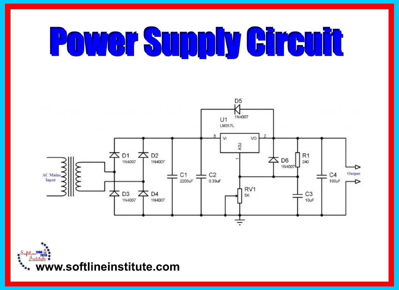
Power supply provides the voltages that printer requires to operate various Printer functions.
The printer require 240VAC, +5VDC , +24VDC, and several high voltage DC and AC values that are used by xerographics.
The printer AC power cord plugs into a grounded AC wall outlet. The cord carries AC line voltage to the noise filter PWB. The noise Filter smoothes the AC voltage and sends it to the Main Power Switch.
Switching on the Main Power Switch applies AC voltage to the AC Driver PWB. And to the Low Voltage Power Supply (LVPS) PWB.
The AC Driver PWB is the interface where between printer control (MCU) and the Fuser.
Fuser sensors connected to the AC driver PWB send Fuser status information to the Driver PWB, which the PWB routes to the MCU PWB.
The MCU processes the information and sends commands back to the AC Driver PWB. To tell the AC driver whether or not to switch on the Fuser Heat rods. The low Voltage Power Supply PWB, or LVPS, converts the 240VAC to regulated +24VDC and +5VDC voltages.
The LVPS sends these voltages to the MCU PWB. The MCU uses the voltages for internal processing and for printer component operation.
The MCU also sends +24VDC to the High Voltage Power Supply PWB.
The High Voltage Power Supply PWB, or HVPS, converts the +24VDC received from the MCU PWB to the high voltages that are required by the xerographic system of the printer.
The HVPS produces the Charge (CR), Transfer (TR) , Developer Bias (DB) and Detack (DTS) vltages, sends them to the Toner Cartridge and to the Bias Transfer Roll (BTR).
Power Supply Components
This printer power supply is made up of following main components and a number of subcomponents.
Noise Filter PWB
Smoothes and removes any fluctuation or hum from the AC line Voltage. Main Power Switch AC voltage on and off (witches the printer on and off).
AC Driver PWB
Receives smoothed AC voltage from the Noise Filter. The AC Driver PWB receives Fuser temperature information from Fuser sensors and passes that information on to the MCU for processing.
The MCU PWB commands the AC Driver to switch on or Switch off AC Voltage to the Fuser Heat Rods.
Low-Voltage Power Supply (LVPS)
Takes filtered AC voltage and converts it into regulated +24VDC ad +5VDC.
-The LVPS contains overcurrent protection circuits. If an excessive current begins to flow through any , the components supplied by the LVPS, the LVPS immediately shuts down all low voltage output.
To reset the LVPS after an overcurrent shutdown; switch off the printer, wait a few minutes, then switch on the printer.
-The LVPS contains open circuit protection circuits. If the LVPS detects that a circuit is open for longer than one minute, the LVPS slowly decreases the LVPS output until the output is zero.
To reset the LVPS after an open circuit shutdown; switch off the printer, wait a few minutes, then switch on the printer.
-The LVPS contains a low +24VDC output protection circuit. If the LVPS detects the +24VDC output dropping below +15VDC, the LVPS slowly decreases the +24VDC LVPS output until the output is zero. -LVPS Fan: A +24VDC fan that cools the LVPS PWB.
Machine Control Unit (MCU PWB)
MCU takes the +24VDC and +5VDC generated by the LVPS and distributes them to the various components through out the printer, including +24VDC to the High Voltage Power Supply (HVPS).
-Interlook Switches SW1 and SW2: Used as a safety measure.
-The main interlook circuit for this printer is actually two separated switches wired in series with the MCU PWB.
-When the EP Cartridge is in the place, Interlook Switches SW1 is closed.
-When the Left Front Cover is closed, Interlook Switch SW2 is closed.
-With both switches closed, the circuit is complete and the MCU PWB sends +24VDC to the HVPS and other Printer Components.
If either SW1 is open (the EP Cartridge removed) or SW2 is open (the Left Front Cover is open) the MCU PWB cuts all +24VDC output from the MCU PWB.
Warning
Even though the interlock switches cut the +24VDC output from the MCU PWB, +24VDC output from the LVPS is still present throughout the printer as well as 240VAC line voltage along the AC paths in the Printer.
High Voltage Power Supply (HVPS)
HVPS take the +24VDC received from the MCU PWB and converts it to the high voltages that are required by the Printer xerographic components.
-The HVPS contains overcurrent protection circuits.
-If an excessive current begins to flow through any of the xerographic components, the HVPS immediately shuts down all high voltage output. To reset the HVPS after an overcurrent shutdown; switch off the printer, wait a feew minutes, then switch off the printer.
